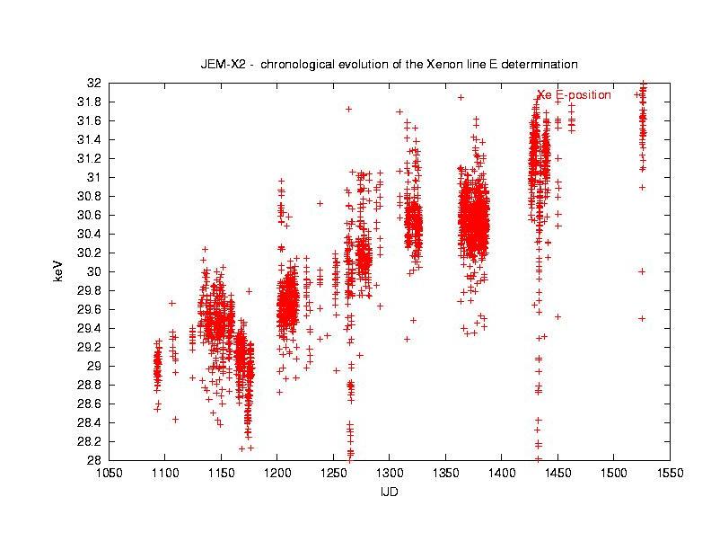
This figure shows the Xe peak position for JEM-X2 during the first part of the mission. The gain correction has been performed using reference values of the calibration peaks and the Xe peak determined during pre-flight calibration. It is clear that these reference channels functioned well at the beginning of the mission. However, the xenon line showed a steady drift upward which needed to be corrected.
The cause of this gain drift is differential gain aging. The relatively lightly irradiated microstrip plate is aging more rapidly than the areas of the plate under the calibration spectra which are heavily irradiated. Consequently, the changing positions of the calibration peaks do not follow the changing position of the Xe line since they change more slowly than the rest of the plate. (Calibration peaks come from only 4 places on the detector while the Xe line is collected from the entire plate).
To counteract this trend, the reference channels for the four calibration lines and the Xe line, for each instrument, have been updated in the IMOD file JMXi-SPAG-MOD, which contains header keywords that store these values. It should be noted from the discussion of gain aging, that the different calibration sources also have changed their positions with respect to each other, and this effect is also covered by updating the reference channel values.
A feature of note in this figure is the dip in the Xe position around about revolutions 50 to 60 (IJD=1150 to 1200). Here the gain of the instrument was very high, just prior to a drop in the high voltage value. When instrument gain is very high, the upper end of the energy scale is affected by the onboard high energy cutoff that removes the higher energy x-ray events as well as the unwanted particle background events. This means that one side of the xenon line is reduced, pushing the effective peak of the line to lower energies.
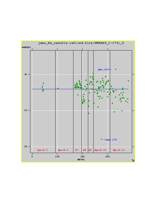
The Xe line is now to be found within 2-3% of the ideal value, 29.6 keV. There is a set of five reference channels for each gain calibration `epoch', shown on the figure with vertical black lines. For JEM-X1 shown here, there are 11 epochs, while for JEM-X2 there are 12.
These epochs were chosen to cover areas of constant instrument configuration, though some of these configuration periods had to be broken up because the gain aging was so fast. This is the case for epochs 8 and 9 for JEM-X1, where we can see that there's a significant difference in the Xenon line position at the ends of the epochs compared to the beginnings. It appears that for both units gain aging first really got going after the units had been activated continuously for several months. Then a period of rapid aging occurred, which has since tailed off for JEM-X1. It is hard to determine the gain aging status of JEM-X2 while it is de-activated.
Two outlying revolutions are labelled on the figure, and you should read the individual notes for these revolutions to understand the special (and very interesting!) problems that arose in the detector environment during these revolutions: 332notes 276notes.
CAO 14/2/2006